Hydraulic flow control valve: principle, type, processing and application
Are you curious about how the excavator’s mechanical arm can be smoothly extended and retracted? How can the tool of the machine tool accurately control the feed speed?
All of this is inseparable from a key component in the hydraulic system – the hydraulic flow control valve.
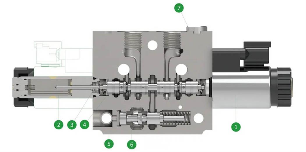
The hydraulic flow control valve is a key component in the hydraulic system, responsible for regulating the flow of the fluid, thereby controlling the speed and power output of the actuator (such as a hydraulic cylinder or motor). In modern industrial equipment, engineering machinery, automobile manufacturing, aerospace and other fields, hydraulic flow control valves are widely used to improve the stability and efficiency of the system.
The flow control of the hydraulic system directly affects the operating efficiency, energy consumption and overall performance of the equipment, so the design and application of the flow control valve is very important. This article will explore the basic principles, main types, production and processing processes and practical applications of hydraulic flow control valves.
1.Working principle of hydraulic flow control valve
The core principle of the hydraulic flow control valve is to control the liquid flow by adjusting the flow area of the throttle. Its main working mechanism includes:
(1) Throttling principle:
When the fluid passes through the throttle, the flow rate and pressure change due to the change of the flow area, thus affecting the flow rate. Different flow characteristics can be achieved by using throttling elements of different shapes, such as orifice plates, slits or conical throttling pieces.
(2) Control method:
1) Manual control:
The operator adjusts the size of the throttle through a knob or lever to meet the needs of specific working conditions.
2) Electrical control method:
Use solenoid valves or servo systems to accurately control the flow rate, which is suitable for automatic control systems.
3) Hydraulic control method:
The valve opening is adjusted with the help of hydraulic signals to achieve automatic adjustment and improve the response speed and stability of the system.
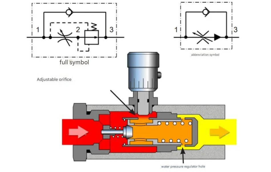
(3) Compensation design:
1) Pressure compensation:
When the system pressure fluctuates, the throttle is automatically adjusted to maintain a stable flow output.
2) Temperature compensation:
When the hydraulic oil temperature changes and the viscosity changes, the throttling parameters are adjusted to maintain a constant flow rate.
3) Feedback regulation:
Use sensor data to monitor flow in real time, and automatically adjust the valve opening through the electronic control system to improve control accuracy.
2.Main types of hydraulic flow control valves
According to their working principles and structural characteristics, hydraulic flow control valves can be divided into the following main types:
(1) Throttle valve
The throttle valve is the simplest flow control valve, which adjusts the flow by changing the cross-sectional area of the flow channel. Its main features are simple structure and low cost, but low flow regulation accuracy.
1) Working principle:
The position of the valve core is adjusted manually or mechanically to change the cross-sectional area of the flow channel, thereby controlling the flow.
2) Types:
Fixed throttle valve: The cross-sectional area of the flow channel is fixed, suitable for occasions where the flow requirement is unchanged.
Adjustable flow valve: The cross-sectional area of the flow channel is adjustable, suitable for occasions where the flow needs to be adjusted frequently.
3) Application:
Commonly used in hydraulic systems that do not require high flow control accuracy, such as small mechanical equipment.
(2) Speed regulating valve
The speed regulating valve is a flow control valve that can maintain a stable flow. Its characteristic is that it can automatically adjust the flow when the load changes to keep the movement speed of the actuator constant.
1) Working principle:
The speed regulating valve is usually composed of a throttle valve and a pressure compensation valve. The pressure compensation valve automatically adjusts the pressure difference before and after the throttle valve according to the load change, thereby maintaining a stable flow.
2) Type:
Ordinary speed regulating valve: suitable for general hydraulic systems.
Speed regulating valve with temperature compensation: can compensate for flow fluctuations caused by changes in oil temperature.
3) Application:
Widely used in construction machinery, machine tools and other occasions where precise control of movement speed is required.
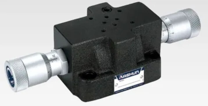
(3) Divider and collector valve
The diverter and collector valve is used to divide an input flow into multiple output flows, or to combine multiple input flows into one output flow.
1) Working principle:
The special structure of the valve core is used to distribute the fluid to different outlets, or to collect the fluid from multiple inlets.
2) Types:
Diverter valve: divides one input flow into two or more output flows.
Flow collector valve: combines two or more input flows into one output flow.
3) Application:
Commonly used in hydraulic systems that require synchronous control of multiple actuators, such as cranes and lifting platforms.
(4) Proportional flow valve
Proportional flow valve is a valve that can accurately control flow through electrical signals. Its characteristics are wide flow adjustment range and fast response speed.
1) Working principle:
The proportional solenoid receives electrical signals and drives the valve core to move, thereby changing the cross-sectional area of the flow channel to achieve continuous flow adjustment.
2) Types:
Direct-acting proportional flow valve: The solenoid directly drives the valve core, which is suitable for small flow occasions.
Pilot-operated proportional flow valve: The main valve core is controlled by the pilot valve, which is suitable for large flow occasions.
3) Application:
Widely used in high-precision control occasions such as automated production lines and CNC machine tools.
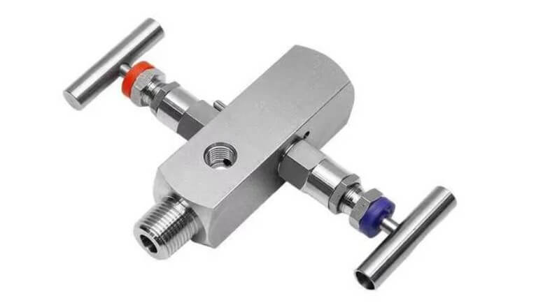
3.Material selection for hydraulic flow control valves
The materials for hydraulic flow control valves need to have high strength, wear resistance and corrosion resistance to meet the requirements of complex working conditions. The main metal materials include:
(1) High-strength alloy steel:
Improve pressure bearing capacity, suitable for high-pressure hydraulic systems, such as heavy engineering machinery and industrial hydraulic presses.
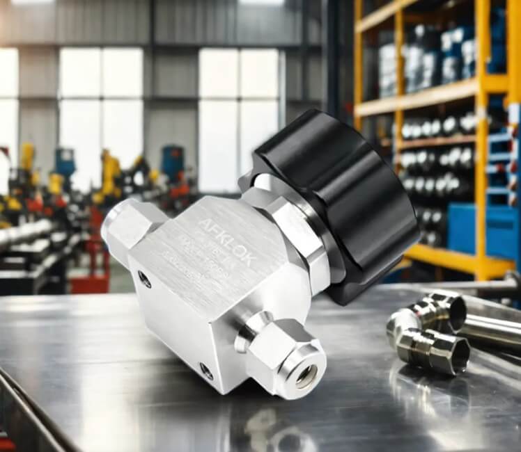
(2) Stainless steel (304, 316L, etc.):
Enhance corrosion resistance, suitable for marine engineering, chemical equipment and food-grade hydraulic systems.
(3) Aluminum alloy:
Lightweight and corrosion-resistant, suitable for aerospace and mobile hydraulic equipment.
(4) Brass:
Good corrosion resistance and machinability, suitable for medium and low pressure hydraulic systems.
(5) Titanium alloy:
Super corrosion resistance and high strength, suitable for special working conditions, such as deep-sea equipment and high temperature and high pressure environments.
(6) Nickel-based alloy:
High temperature and corrosion resistance, suitable for extreme working conditions, such as high temperature hydraulic systems in the oil and gas industry.
In addition, some non-metallic materials such as engineering plastics, ceramics and composite materials are also used to meet specific application requirements.
4.Production and processing of hydraulic flow control valves
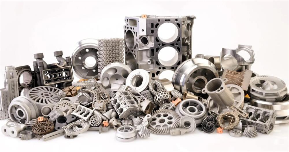
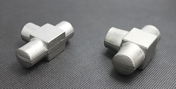
(1) Precision casting
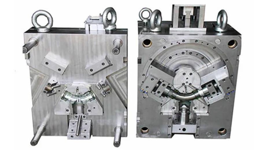
● Use high-precision molds to manufacture valve bodies with complex structures to ensure the flow characteristics of the internal channels.
● Use advanced investment casting (lost wax casting) technology to improve the surface finish and dimensional accuracy of parts.
● Perform heat treatment to improve the strength, toughness and wear resistance of the material.
● Use X-ray detection and non-destructive testing technology to ensure that the castings have no internal defects and improve product reliability.
(2) CNC precision machining
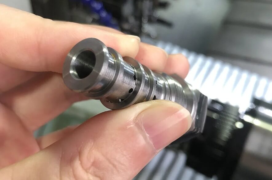
● Use high-precision CNC machine tools to process key components such as throttles and valve cores to ensure smooth flow channels, reduce flow resistance, and improve valve sealing and control accuracy.
● Use five-axis or multi-axis machining centers to improve the machining accuracy and consistency of complex structural components.
● Perform precision grinding and polishing to ensure the surface finish of parts, reduce hydraulic oil pollution, and improve system reliability.
● Real-time monitoring of processing errors through automatic detection systems to improve batch production consistency.
(3) Surface treatment
1) Chrome plating: Improve wear resistance, prevent corrosion, and increase service life.
2) Oxidation treatment: Enhance antioxidant capacity and improve adaptability in harsh environments.
3) Nickel plating: Improve fluid compatibility and is suitable for high-purity hydraulic systems.
4) Nano coating: Reduce friction, improve durability and corrosion resistance.
(4) Seal manufacturing and installation
● Use high-temperature and wear-resistant rubber or polymer materials such as fluororubber or polytetrafluoroethylene (PTFE).
● Use automated assembly to improve assembly accuracy, reduce human errors, and improve product consistency.
5.Application scenarios of hydraulic flow control valves
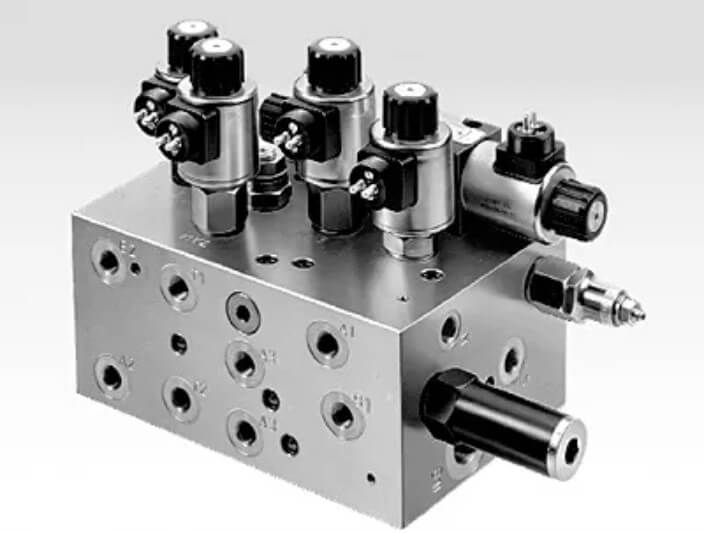
(1) Industrial equipment
Machine tools, hydraulic presses and other equipment require precise control of the movement speed of the hydraulic cylinder to improve processing accuracy and production efficiency.
(2) Engineering machinery
Excavators, loaders and other equipment need to adjust the flow according to the load to improve operating efficiency and reduce fuel consumption.
(3) Aerospace
High-precision hydraulic flow control valves are required in aircraft landing gear and fuel control systems to ensure flight safety.
(4) Automobile Manufacturing
Power steering systems and automatic transmissions require stable flow regulation to improve driving comfort and fuel economy.
(5) Renewable Energy
In wind and solar power generation systems, hydraulic flow control valves are used to optimize the energy conversion process and improve energy utilization.
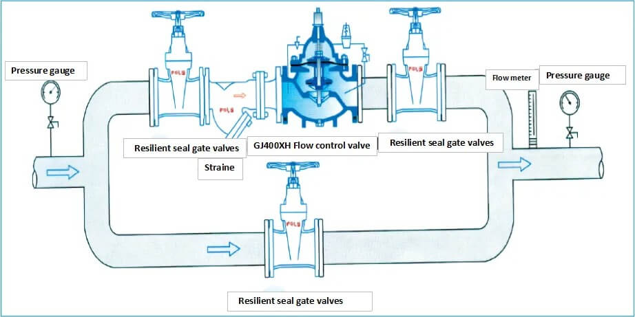
(6) Oil and Gas Industry:
Used in drilling platforms and pipeline transportation systems to ensure flow control and safe operation in harsh environments.
(7) Shipbuilding and Marine Engineering:
Used in ship propulsion systems, deck lifting equipment and deep-sea exploration equipment.
5.Summary
In summary, although hydraulic flow control valves are small in size, they play a vital role in hydraulic systems. They are like the “commanders” of hydraulic systems, accurately adjusting the flow and direction of the fluid, ultimately achieving precise movement and efficient operation of mechanical equipment.

